
An Engineer’s Honest Assessment — Network Engineering Deep Dives — Updated July 2026

When MPLS breaks in a service provider or enterprise WAN, it breaks quietly. A BGP session stays up. OSPF adjacencies remain established. Ping works. But user traffic stops flowing across the backbone, VPN routes disappear from the routing table, and a 15-branch enterprise loses connectivity to its data centre — while every monitoring tool shows green. This is the specific cruelty of MPLS failure: the control plane and forwarding plane can diverge silently, and the engineer who does not understand how labels are distributed and forwarded will chase the wrong problem for an embarrassingly long time.
Mastering MPLS unlocks something beyond the certification tick. You gain the ability to read a Label Forwarding Information Base as fluently as a routing table, diagnose LDP session failures before they cascade into VPN outages, and design MPLS L3VPN topologies that cleanly separate customer routing without confusing route distinguisher and route target every time. For engineers targeting CCIE SP, JNCIP-SP, or moving from enterprise to service provider roles, MPLS is not one topic among many — it is the foundational layer that every advanced SP technology sits on.
| Disclaimer General: The NetDaemons team has researched and cross-checked technical claims, CLI syntax, RFC references, and platform behaviour at time of writing (July 2026). CLI behaviour and vendor implementation details change with software releases — verify against your platform version before applying in production. Platform versions: CLI examples are written for Cisco IOS-XE 17.x and Junos 22.x. Behaviour on IOS-XR or earlier Junos releases may differ — noted where significant. Verdicts: All design recommendations reflect the independent technical assessment of the NetDaemons team, based on deployment experience and published documentation. This article contains affiliate links — resource links will carry tracked URLs once affiliate programmes are approved. |
1. What MPLS Actually Is — and What Problem It Solves
At its core, MPLS solves one problem: IP forwarding decisions are expensive when made independently at every hop. A router receiving an IP packet must look up the destination address in a potentially large routing table, determine the next hop, and rewrite the Layer 2 header — at every single transit router in the path. In a carrier backbone carrying hundreds of thousands of routes, this per-hop IP lookup is a real processing cost.
MPLS moves the forwarding decision to the network edge. The ingress edge router — the Label Edge Router, or LER — classifies each packet into a Forwarding Equivalency Class (FEC): a group of packets that will follow the same path and receive the same treatment. It attaches a label: a 32-bit value inserted between the Layer 2 header and the IP header, sometimes called the “shim header”. Every transit router — the Label Switch Router, or LSR — makes its forwarding decision by looking up only that label in its Label Forwarding Information Base (LFIB), swapping the incoming label for an outgoing label, and forwarding. No IP lookup. No route table traversal. One table lookup, one label swap, one forwarding decision.
The MPLS Label: Four Fields, 32 Bits
The label is a 32-bit structure inserted after the Layer 2 header and before the IP header. Each field has a specific function:
| Field | Bits | Purpose |
| Label Value | 20 | The actual forwarding identifier. Values 0–15 are reserved; 16–1,048,575 are usable. The LSR looks up this value in the LFIB. |
| Traffic Class (TC) | 3 | QoS marking — maps to IP DSCP/CoS at ingress and is used for PHB treatment at each LSR. Originally called the EXP field; renamed TC by RFC 5462. |
| Bottom of Stack (BoS) | 1 | Set to 1 on the innermost (bottom) label in a label stack. A value of 0 means more labels are above the IP header. LSRs use this bit to determine when to expose the IP layer. |
| TTL | 8 | Decremented at each LSR, same as IP TTL. By default, the IP TTL is copied into the MPLS TTL at label imposition and written back at disposition. |
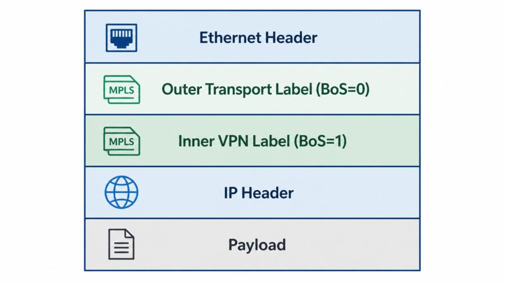
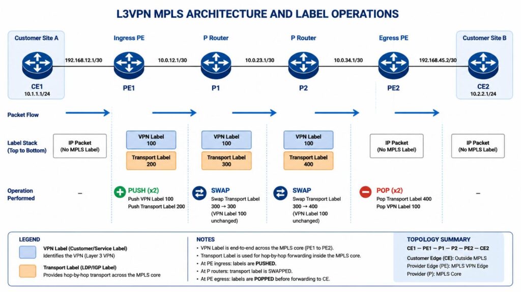
Labels can be stacked. In an MPLS VPN, a packet typically carries two labels: a VPN (inner) label identifying the customer VRF at the egress PE, and a transport (outer) label routing the packet across the backbone. The outermost label is always used for forwarding. Reading a label stack means reading it from top (outermost) to bottom (BoS=1).
. How MPLS Actually Works: The Label Forwarding Path
Three things must be in place before MPLS can forward traffic: a running IGP (OSPF or IS-IS in most deployments), a label distribution protocol to exchange labels between routers, and a compatible data plane that can push, swap, and pop labels. The control plane builds the Label Information Base (LIB). The forwarding plane builds the LFIB from the LIB, filtered by the IGP next-hop. Both are distinct tables — a critical distinction for troubleshooting.
Label Distribution Protocol (LDP)
LDP is the most common label distribution protocol in enterprise and SP environments. Its operation has three phases:
Discovery: LDP routers send UDP hellos to the multicast address 224.0.0.2 on port 646. Any LDP-capable router on the same segment responds. Extended (targeted) LDP discovery sends unicast hellos to a specific address — required when establishing an LDP session between non-adjacent routers, as is common for MPLS TE tunnel head-ends and LDP over traffic-engineered tunnels.
Session establishment: After discovery, the two routers establish a TCP session on port 646. The router with the higher LDP Router ID becomes the active peer and initiates the TCP connection. An LDP session is entirely separate from any IGP neighbour relationship — LDP can be up while OSPF is reconverging, which creates a brief but important window where labels exist for destinations the IGP cannot yet reach.
Label binding: Cisco IOS uses liberal label retention mode by default. This means a router accepts and stores label bindings from ALL LDP peers, not only the one currently installed as the IGP next hop. The benefit: when the IGP reconverges and elects a new next hop, the label for that next hop is already in the LIB — LDP does not need to re-advertise. This trades memory for convergence speed, and in most deployments the trade is correct.
Key LDP Verification Commands
On Cisco IOS-XE:

On Junos:

Penultimate Hop Popping (PHP)
The egress LER would normally perform two operations: pop the outermost MPLS label, then do an IP lookup to deliver the packet. PHP offloads the label pop to the second-to-last router (the penultimate hop). The penultimate router pops the transport label before forwarding, so the egress LER receives either a plain IP packet (single label) or just the inner VPN label (stacked labels) and performs only one lookup.
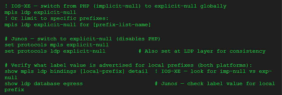
Both Cisco IOS-XE and Junos signal implicit null (label value 3) by default for their own loopback and directly connected prefixes when running LDP — PHP is the default on both platforms. Implicit null tells the penultimate hop to pop the label rather than swap it, so the egress LER receives either a plain IP packet (single label) or only the inner VPN label (stacked) and performs a single lookup. Label value 0 is explicit null: the penultimate hop swaps to 0 rather than popping, which preserves TC bits all the way to the egress LER. This distinction matters for DiffServ-aware traffic engineering — with implicit null, TC bits are lost at the penultimate hop; with explicit null they reach the egress LER intact for correct PHB treatment.
Junos LDP also signals implicit-null by default — PHP is the standard behaviour on both platforms. The command to switch to explicit-null on each platform is:
MPLS MTU: The Silent Killer
Every pushed label adds 4 bytes. A standard Ethernet frame with an MTU of 1500 bytes can carry a 1500-byte IP packet on a pure IP path. Add one MPLS label and the effective IP payload drops to 1496 bytes. Add a two-label VPN stack and it drops to 1492 bytes. In most SP backbone deployments, backbone interfaces are configured with a larger MTU (typically 1508, 9000, or jumbo frame capable) to absorb the label stack without fragmenting IP traffic.
The failure mode: a customer sends 1500-byte packets, the SP backbone has standard 1500-byte MTU on backbone interfaces, and the MPLS overhead causes fragmentation or silent drops at every P router. The customer reports intermittent connectivity — small packets work, large packets drop. The fix requires either increasing the backbone MTU or reducing the CE MTU.
IOS-XE — set MPLS MTU per interface:

Junos — MTU is configured at the interface level and applies to MPLS automatically:

LIB vs LFIB: Two Tables, Two Planes
The Label Information Base (LIB) is the control plane store — it holds all label bindings received from all LDP peers, including bindings for prefixes whose next hop is not currently an LDP peer. It is the equivalent of the BGP table: comprehensive but not directly used for forwarding. The LFIB is the forwarding plane — it holds only the label bindings that correspond to the IGP’s currently installed next hops. When a prefix has an LDP binding in the LIB but does not appear in the LFIB, the IGP next hop for that prefix is not an LDP neighbour. MPLS forwarding is not active for that destination even though LDP is aware of it. This is a common source of confusion in troubleshooting VPN connectivity — the control plane looks healthy, the forwarding plane is missing an entry.
3. Where Engineers Get MPLS Wrong
1. Assuming an IGP neighbour is also an LDP neighbour
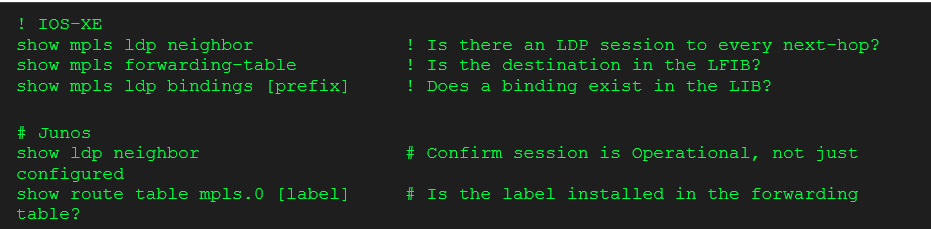
LDP sessions and IGP neighbour relationships are completely independent. You can have an established OSPF adjacency with a router that is not running LDP and LDP will not signal any error — it simply will not establish a session. Traffic to prefixes reachable via that non-LDP hop will fall back to plain IP forwarding (label imposition fails, the packet is forwarded without a label). In a pure IP network this is invisible. In an MPLS VPN it is fatal — VPN routes require label switching all the way to the egress PE. Debug this first when VPN routes are present but traffic is not flowing:
2. Ignoring LDP-IGP synchronisation
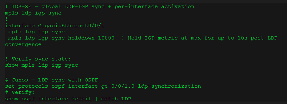
When a link comes up, the IGP converges and installs the new next hop before LDP has established a session and exchanged labels on that new link. During this convergence window — which can run from one second to several seconds depending on IGP timer tuning — the IGP routes traffic over the new link but MPLS label forwarding for that path has not been set up. In a pure IP network this window is invisible. In an MPLS network, traffic requiring label switching (VPN traffic, TE tunnels) is black-holed during this window. This failure is most common after link flaps in hub-and-spoke WAN topologies where LDP convergence lags the IGP.
LDP-IGP synchronisation (RFC 5443) addresses this by holding the IGP metric at maximum cost on a new link until LDP convergence is confirmed. Enable it on every MPLS-capable interface:
3. Confusing Route Distinguisher and Route Target
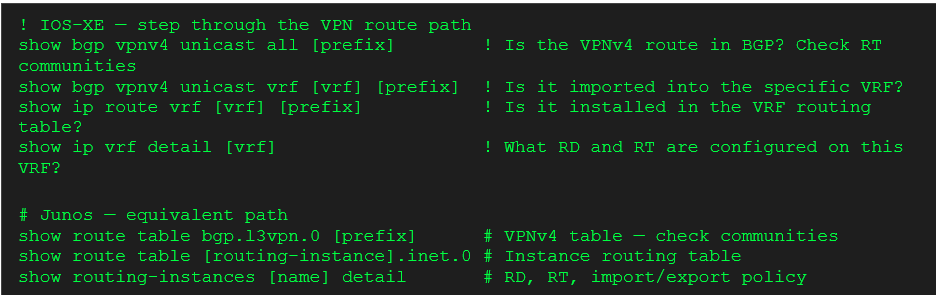
This is the most common conceptual mistake in MPLS L3VPN. The Route Distinguisher (RD) and Route Target (RT) are distinct constructs with distinct purposes. The RD makes a VPN prefix globally unique in the BGP table — it prepends an 8-byte value to a customer IP prefix to create a VPNv4 route. Its only job is to prevent address space collisions between customers using the same private IP range (two customers can both use 10.0.0.0/8 without colliding in MP-BGP, because their RDs differ). The RD has zero import/export semantics.
The RT is an extended BGP community attached to VPNv4 routes. It controls which VRF imports which routes. A PE exports routes tagging them with an export RT; it imports routes matching its import RT policy. A VPN route can sit in MP-BGP indefinitely and never appear in a customer VRF if the RT import policy is misconfigured — even though the RD is correct and the route is visible in the BGP table.
Verification ladder when VPN routes are missing from a VRF:
4. CEF dependency on Cisco platforms
MPLS forwarding on Cisco platforms is built on top of Cisco Express Forwarding (CEF). If CEF is disabled on an interface, MPLS label switching will not function on that interface regardless of LDP session state. On older IOS configurations migrated from process-switching environments, this is occasionally encountered. Verify CEF is enabled and consistent before troubleshooting MPLS:

5. TTL propagation exposing the backbone
By default, the IP TTL from the packet is copied into the MPLS TTL at label imposition and decremented at each LSR. This means a traceroute from a customer CE shows every LSR in the SP backbone path — allowing customers to map backbone topology. Service providers routinely disable TTL propagation at PE routers to hide the backbone from customer visibility:

Without this command, a customer can identify every transit router in the SP backbone by running traceroute. This is both a commercial sensitivity issue (revealing backbone topology to competitors who are also customers) and a potential security exposure. Most carriers enable this by default.
| From the field — LDP-IGP synchronisation gets configured correctly during initial MPLS builds and then breaks silently during capacity expansions or circuit changes. In a Middle East enterprise WAN deployment using a Tier-1 carrier’s MPLS L3VPN service, with an FTTH circuit configured as the backup path for one site, we observed a recurring 2-second traffic black-hole on every failover. OSPF was reconverging in under 900ms — well within expected parameters. The problem was LDP: the session on the FTTH backup interface was taking approximately 2.8 seconds to re-establish and exchange label bindings after the circuit came up. During that gap after OSPF convergence, labelled VPN traffic was being routed over the backup interface with no corresponding LFIB entries — the router was label-imposition-capable for that path in the control plane but had no forwarding entries. Configuring LDP-IGP sync holddown of 3000ms on the backup interface — tuned to slightly exceed the observed LDP convergence time — eliminated the black-hole window completely. |
4. Design Considerations for Production MPLS Networks
MPLS L3VPN Architecture (RFC 4364)
An MPLS L3VPN connects geographically separated customer sites over an SP backbone while keeping each customer’s routing completely isolated from the provider core and from every other customer. The architecture has four elements:
| Element | Role and complexity |
| CE | Customer Edge — the customer router facing the SP. Runs a simple routing protocol (OSPF, eBGP, or static) with the PE only. The CE has no awareness of MPLS, labels, or VRFs. |
| PE | Provider Edge — the SP router where all complexity lives. Maintains a per-customer VRF. Runs CE-PE routing protocol in VRF context. Distributes VPNv4 routes via MP-BGP to other PEs. |
| P | Provider core — LSRs in the SP backbone. Swap MPLS labels only. Have zero awareness of customer VPNs, VRFs, or IP prefixes. This is the scalability advantage: P routers stay simple. |
| MP-BGP | Multiprotocol BGP carrying VPNv4 address family. Distributes customer VPN routes between PEs, carrying the RD-prefixed prefix plus RT extended communities. Runs only between PE and Route Reflectors — P routers are not BGP speakers. |
Forwarding uses a two-label stack. The inner (VPN) label identifies the egress VRF and is distributed by the egress PE via MP-BGP. The outer (transport) label switches the packet across the backbone to the egress PE and is distributed by LDP (or RSVP-TE for TE paths). The outer label is swapped at every P router; P routers never see the inner VPN label or any IP prefix. The inner label is processed only at the egress PE.
Route Reflector Design in MPLS Networks
In an SP network with many PEs, a full mesh of MP-BGP sessions between every PE pair is unscalable — N*(N-1)/2 sessions for N PEs. Route Reflectors (RRs) solve this: PEs peer with the RR as clients, and the RR reflects VPNv4 routes between them. Design decisions:
• Place RRs in or near the network core — they must be reachable from all PEs via the IGP, and their loopback addresses must be stable.
• RRs do not need to be in the forwarding data path. They handle only the BGP control plane. A dedicated server or VM running BGP can function as an RR.
• Deploy at minimum two RRs per cluster, with each PE peering with both. Split the RR cluster only when scale demands it.
• Critical: the RR must not modify the NEXT_HOP attribute when reflecting VPNv4 routes. The egress PE’s loopback IP remains the BGP next hop. The transport label for that loopback is resolved by LDP in the forwarding plane — the RR is invisible to the forwarding path.
• In multi-AS deployments (Inter-AS Option B or C), RR placement becomes more complex. Approach Inter-AS MPLS only after single-AS is fully understood.
Traffic Engineering with RSVP-TE
LDP builds Label Switched Paths that follow the IGP shortest path. If you need to control which physical path traffic takes — for load balancing, bandwidth reservation, or path diversity — LDP cannot help you. RSVP-TE (Resource Reservation Protocol — Traffic Engineering) allows explicit path specification and bandwidth reservation along an engineered path.
An RSVP-TE tunnel is configured at the head-end router. It signals a Label Switched Path along an explicit or constrained route using RSVP PATH and RESV messages. Each LSR in the path allocates bandwidth from its resource pool and installs the label binding. The key operational requirement: MPLS-TE must be enabled on every interface in the potential path, and the Traffic Engineering Database (TED) must be populated via OSPF-TE or IS-IS-TE extensions — the IGP must advertise link bandwidth and TE metrics for CSPF to compute paths.
RSVP-TE adds operational complexity that most enterprises do not need. Justify it when: you need sub-50ms FRR convergence, when load balancing across equal-cost paths is insufficient, or when you need bandwidth-guaranteed paths for specific traffic classes. For most enterprise MPLS VPN deployments, LDP is adequate.
MPLS Fast Reroute (FRR)
MPLS FRR provides convergence faster than the IGP can deliver by pre-computing a backup LSP before any failure occurs. When a link or node failure is detected (via BFD or RSVP hello timeout), the Point of Local Repair (PLR) immediately switches traffic to the pre-built bypass tunnel — in the data plane, before the IGP has even begun converging. The target is sub-50ms switchover.
FRR requires RSVP-TE. Two protection modes:
Link protection: the bypass tunnel goes around the failed link to the next router in the primary path. Protects against link failures only.
Node protection: the bypass tunnel goes around both the failed link and the next-hop router. Protects against both link and node failures. Preferred for production deployments.
LDP vs SR-MPLS: The Migration Direction
Segment Routing with MPLS data plane (SR-MPLS) is the direction for new SP deployments, particularly in Indian operator networks where SR-MPLS rollouts on IOS-XR (Cisco ASR9000, NCS series) and Juniper MX are active. SR-MPLS uses IGP extensions (OSPF-SR, IS-IS-SR) to distribute labels — no separate LDP protocol is required. Every router advertises a Node SID (a globally unique label index) and optionally Adjacency SIDs (locally significant labels for specific links).
The operational simplification is real: no LDP sessions to maintain, no LDP-IGP sync issues, and TE paths can be encoded in the packet header using a label stack without RSVP signalling (Segment Routing Traffic Engineering, or SR-TE). Existing LDP networks can be migrated incrementally using a Segment Routing Mapping Server to redistribute LDP labels into SR, or by running both protocols simultaneously during migration.
SRv6 (Segment Routing over IPv6) takes this further by encoding the segment list in an IPv6 extension header, removing the label plane entirely. SRv6 is in active deployment in Chinese and Japanese SP networks; Indian operators are in early trials. This doesn’t affect most enterprise engineers today, but CCIE SP and JNCIP-SP candidates should understand the SR-MPLS → SRv6 trajectory.
| From the field — The consistent observation across MPLS modernisation discussions with Indian Tier-2 operators is that the SR-MPLS migration blocker is almost never the core network — it is the CE base. PE platforms running IOS-XR 6.3+ and Junos 17.2+ have native SR-MPLS support. The constraint is the enterprise CE routers connecting to those PEs: platforms running IOS 15.x or even earlier that have no SR capability and cannot be refreshed on the SP’s schedule. The correct approach for this coexistence window is SR-MPLS in the core, with the Segment Routing Mapping Server (SRMS) maintaining LDP-to-SR label interworking for legacy CE-connected PEs. The single design decision that most consistently causes problems during migration is the SRGB (Segment Routing Global Block) range definition: if the SRGB overlaps the LDP dynamic label range, label conflicts produce forwarding loops that are genuinely difficult to diagnose under traffic. Always define the SRGB explicitly — on Cisco IOS-XR, the range 16000–23999 is standard for most greenfield deployments — and verify the LDP dynamic range begins above it before any SR-MPLS cutover. |
5. Real-World Scenario: Indian Enterprise MPLS L3VPN — 15 Branches, Two VRFs
An Indian manufacturing company has its primary data centre in Chennai and 15 branch offices spread across Maharashtra, Gujarat, Karnataka, and Tamil Nadu. The company purchases a commercial MPLS L3VPN service from a Tier-1 Indian SP running IOS-XR at the PE layer. The network architect must design the CE-PE routing and ensure strict VRF separation between the corporate LAN segment and a POS/guest DMZ segment that must never reach corporate resources directly.
CE-PE Routing Decision
The SP offers both OSPF and BGP for CE-PE routing. BGP is preferred for this deployment for three reasons: it allows clean redistribution control at the CE without risk of accidentally leaking internal OSPF routes into the SP; BGP communities can be used to tag routes for policy control at the PE without touching SP configurations; and the CE-SP demarcation is cleaner — troubleshooting is simpler when the CE is clearly ‘inside’ and the PE is clearly ‘outside’ a BGP boundary.
VRF Design at the PE
The SP creates two VRFs per site: CORP_SITE_<n> for corporate traffic and GUEST_SITE_<n> for the POS/DMZ segment. The RD is unique per VRF per PE — e.g. 65000:1001 for CORP_CHENNAI, 65000:2001 for GUEST_CHENNAI. The RT policy is:
Corporate VRFs — hub-and-spoke RT design: A hub-and-spoke MPLS VPN requires two distinct Route Targets — one for spoke export and one for hub export. Using identical import/export RTs on all VRFs would create a full mesh, allowing branches to reach each other directly and bypassing the Chennai firewall. The correct design: spoke site VRFs export RT 65000:100 and import only RT 65000:101. The Chennai hub VRF exports RT 65000:101 and imports RT 65000:100. Result: the hub receives all spoke routes (imports RT 65000:100, which every spoke exports), and all spokes receive only hub routes (import RT 65000:101, which only the hub exports). Spokes have no direct route to any other spoke — all branch-to-branch traffic must transit Chennai.
Guest/DMZ VRFs: export RT 65000:200 only — no import RT is configured, so no routes are imported from any other VRF. Guest traffic can reach the internet via a breakout at the PE or a dedicated internet VRF, but has zero control-plane path to any corporate resource. This is enforced at the MPLS control plane — not dependent on firewall policy alone.
Verification Commands: End-to-End
At the CE (Cisco IOS-XE branch router):

At the PE (IOS-XR — SP may share this output during escalated troubleshooting):

If a branch loses connectivity to the DC, the escalation path is: verify CE BGP session → verify VPN route in CE table → verify VPN route in PE VRF → verify VPNv4 route in MP-BGP between PEs → verify LFIB entry at egress PE → check physical path with traceroute. Working through this ladder systematically takes less than five minutes once you know which table each step checks.
| From the field — In MPLS L3VPN deployments with Indian SP networks (Tata Communications, Airtel, BSNL, Jio Enterprise), direct PE access is almost never granted to the customer. All MPLS troubleshooting happens from the CE side, and the diagnostic discipline is specific. Three commands carry most of the diagnostic weight: show ip bgp neighbors [PE-IP] received-routes confirms exactly which VPN routes the PE is advertising into this site’s VRF — if routes are absent here while the BGP session shows Established, the cause is almost always RT misconfiguration at the PE or a VRF import policy failure. This is an SP-side issue, not a CE issue, and the only resolution path is raising an escalation with the specific missing prefix and the expected RT value. show ip bgp [prefix] detail reveals the BGP NEXT_HOP attribute — if the NEXT_HOP address is not reachable in the CE routing table, BGP accepts the route but does not install it, producing the misleading result of a healthy BGP session with no working connectivity. traceroute source [CE-loopback] with progressively increasing TTL values is often the only tool available to fingerprint SP-side MPLS path behaviour. If all intermediate hops return asterisks, TTL propagation is disabled at the PE — standard SP practice to hide backbone topology, not a fault. If the first response comes from an unexpected address, a routing or label forwarding asymmetry exists on the SP network and the MPLS path has likely shifted to a backup. |
6. When to Move On From MPLS
MPLS is a mature technology. In SP cores it will remain relevant for another decade minimum. In enterprise WAN, the decision calculus has shifted — and understanding when to transition is as important as understanding how MPLS works.
| Move away from dedicated MPLS WAN when: | Stay with MPLS when: |
| • Cost pressure is significant — MPLS circuits cost significantly more per Mbps than broadband internet in India and globally • Branch count is growing faster than budget — SD-WAN can onboard a new site in hours vs weeks for MPLS provisioning • Cloud and SaaS traffic dominates — backhauling Microsoft 365 or AWS traffic via a DC hub over MPLS is architecturally wasteful • Application mix has shifted — when WAN is 80% web, SaaS, and video conferencing, MPLS QoS differentiation is less relevant than it was for SAP + voice on a single pipe | • SP-grade SLA is non-negotiable — financial institutions, hospitals, government entities with hard uptime and latency commitments • Latency-sensitive real-time traffic dominates — manufacturing SCADA, trading platforms, healthcare imaging where broadband jitter is not acceptable • Security posture prevents internet exposure — segments requiring zero internet connectivity on the WAN path; dedicated MPLS satisfies this requirement cleanly • Compliance mandates a private WAN — certain regulatory frameworks (RBI guidelines for core banking in India) effectively mandate dedicated private connectivity |
Most enterprises are moving toward hybrid WAN: MPLS for latency-critical and compliance-driven applications, SD-WAN over broadband for everything else. The practical challenge is identifying which applications genuinely require MPLS-grade QoS and which ones are on MPLS because of historical inertia rather than actual requirement.
INTERNAL LINK: See our SD-WAN vs MPLS deep dive for a full cost and performance comparison in Indian enterprise deployments
7. Certification Angle — CCNP / CCIE SP / JNCIP-SP
MPLS appears in CCNP ENCOR at a conceptual level. It goes deep in CCNP Service Provider (Implementing Cisco Service Provider Network Core Technologies — SPCOR 350-501) and is foundational for CCIE SP. JNCIP-SP and JNCIE-SP treat MPLS as the central technology — the entire service provider track is built on MPLS L3VPN and L2VPN, with SR-MPLS now appearing in advanced topics.
What the exam tests vs what production requires
| Topic | Exam focus | Production adds |
| MPLS L3VPN | Configure VRF, RD, RT, CE-PE BGP/OSPF, MP-BGP between PEs. Verify with show commands. Know the label stack. | Debugging SP PE routers when you have read-only access at best. Escalation procedures. RT misconfiguration is almost always the culprit for missing VPN routes. |
| LDP | LDP neighbour establishment, label bindings, PHP, label values 0 and 3 | LDP-IGP sync on flapping links. LDP session resets from TCP resets (firewall blocking port 646). MTU issues on specific circuit types. |
| RSVP-TE / FRR | Explicit path tunnel configuration, FRR bypass tunnel, protection modes | BFD tuning for FRR trigger timing. RSVP path re-optimisation after link recovery. Traffic engineering database synchronisation after OSPF-TE advertisement. |
| SR-MPLS | SPCOR exam now includes SR-MPLS topology. Node SID, Adjacency SID, SR-TE policy basics. | Inter-working between LDP and SR domains during migration. Mapping Server configuration. IOS-XR-specific SR CLI differs from IOS-XE. |
| From the field — The CCIE SP practical lab will ask you to configure MPLS L3VPN end-to-end and verify specific show command outputs under time pressure. Know show bgp vpnv4 unicast all, show mpls forwarding-table, and show ip route vrf cold — you will need to read them without pausing to recall the syntax. For JNCIP-SP, the Junos routing-instances model (set routing-instances CORP instance-type vrf) is meaningfully different from Cisco VRF syntax — practise both in the lab before sitting either exam. |
INTERNAL LINK: BGP Explained for Enterprise Engineers — relevant for understanding the MP-BGP control plane used by MPLS L3VPN
8. Recommended Study and Lab Resources
INE MPLS and CCIE SP Track
The most technically complete treatment of MPLS forwarding, LDP, RSVP-TE, L3VPN, and now SR-MPLS for CCIE SP and JNCIP-SP preparation. INE’s MPLS VPN module goes significantly beyond what certification study guides cover — particularly on route policy design and multi-AS VPN. If you are studying for CCIE SP, this is the primary paid resource.
CBT Nuggets CCNP SP — MPLS and L3VPN Modules
More accessible than INE for engineers coming from an enterprise CCNP background who are encountering MPLS at depth for the first time. The L3VPN module is well-structured and the show command walkthroughs are particularly strong. Use alongside GNS3 or CML lab time for maximum retention.
Boson ExSim for CCIE SP Written
For CCIE SP candidates, Boson’s written exam simulator is the closest available approximation of the real exam for MPLS topics. The scenario-based questions on L3VPN troubleshooting and TE path selection are particularly useful. If you consistently score above 850 on Boson MPLS topics, you are ready for the written component.
Free Lab Options
Cisco Modelling Labs (CML) Personal Edition provides IOS-XE and IOS-XR images in a browser-based lab environment — the right platform for MPLS L3VPN end-to-end practice without physical hardware. GNS3 with IOS images is the free alternative, though IOS-XR images require a Cisco account. For Junos MPLS practice, Juniper vLabs provides free access to vSRX and vMX environments — use these specifically for Junos routing-instances and LDP configuration practice.
Team NetDaemons Verdict
The following reflects the independent assessment of the NetDaemons team. Apply these principles against your specific environment — platform version, SP relationship, and traffic profile all influence which recommendations are relevant.
| NetDaemons take: Understand MPLS as two completely separate planes before touching any configuration. The control plane (LDP distributing labels, MP-BGP distributing VPN routes) and the forwarding plane (label push/swap/pop in the LFIB) can diverge silently. When something breaks: identify which plane has failed first. An LDP session is up but traffic is not flowing? Check the LFIB, not the LIB. VPN routes appear in MP-BGP but not in the customer VRF? Check the RT import policy, not the RD. That diagnostic discipline makes MPLS troubleshooting systematic rather than reactive. |
| NetDaemons take: For engineers considering an MPLS-to-SD-WAN migration, do not treat MPLS knowledge as legacy. Understanding what MPLS was doing for your traffic — QoS treatment, path determinism, isolation — tells you exactly what SD-WAN overlay policy needs to replace. Engineers who migrate without this understanding typically discover six months later that critical applications were relying on MPLS QoS classes they had not documented. |
Studying for CCIE SP or JNCIP-SP: spend one week doing nothing but building MPLS L3VPN topologies in the lab from scratch. Add a second PE, a new VRF, a new CE. Break the RT policy deliberately and diagnose it. Add LDP-IGP sync and observe the holddown behaviour during a link flap. The show commands should feel instinctive before you sit the exam — because under time pressure, fluency with the verification ladder is what separates candidates who pass from those who know the theory but run out of time.
Questions about your specific MPLS deployment, SP handover, or migration design? Drop them in the comments — we read and respond to every one.
Related Articles
| Article | Why it is relevant | Status |
| What is SD-WAN? Complete Guide for IT Managers and CIOs | Foundational overview of what replaces MPLS in hybrid WAN architectures | ✅ LIVE |
| BGP Explained for Enterprise Engineers | MP-BGP is the control plane for MPLS L3VPN — understanding BGP path selection is essential for VPN troubleshooting | ✅ LIVE |
| CCNP Enterprise vs JNCIP-EN — Which Certification is Worth Your Time in 2026 | Next certification decision after mastering MPLS fundamentals | Coming October 2026 |
netdaemons.com · Network Engineering Deep Dives · July 2026 · CLI syntax verified for Cisco IOS-XE 17.x and Junos 22.x at time of writing. Verify against your platform version before applying in production. This article contains affiliate links — resource links will carry tracked URLs once affiliate programmes are approved.